BUILDING THE WB2HOL FOXHUNTING BEAM
PLEASE NOTE: The Yagi described on this page is designed to be used with a receivers linked with a coax feed. There are other pages on this site describing integrated yagi/receiver solutions.
The design of the WB2HOL 2m tape measure yagi shows a great piece of lateral thinking, it is also is proven to be highly practical for fox hunts and ARDF. The elements will withstand those reckless charges through the undergrowth in pursuit of the fox, they also make it easy to get the beam in and out of the car with little risk of damaging either the car or the antenna.
I first built one of these beams for my own use (circa 2000) , but when asked to produce a batch for the club, I had to rethink about the construction.
My original was constructed with components from my ‘junk box’ so would be difficult to repeat.
The original WB2HOL design is unbeatable for simplicity, but the 4-way pipe connectors used to support the elements are not generally available in the UK.
After several failed attempts to use T-piece connectors and various pipe clips to support the elements I finally opted to use a 2-hole-fixing plastic saddle clip, designed for the Marley 21.5mm overflow system.
My design requires some extra drilling and cutting of the elements and boom, this has to be done reasonably carefully, to ensure correct alignment of the elements ….
however … it is not a difficult job because the PVC material is very soft and easy to work.
Tip: Most plastic pipe made for piping (e.g. Speedfit) is too soft to be usable for the boom. PVC electrical conduit is OK but the diameter is smaller (20mm) so not suitable for use with the Marley saddle clips.
25mm (1″) tape is a lot stiffer than 20mm (3/4″) and cheaper per metre! Your local DIY store should sell a budget 8m or 10m tape for less than £5.
The dimensions of the beam are shown in fig 1. These have been scaled up from the original design for operation at 145mHz. This frequency is mid way between the clubs foxhunt channel (145.425) and the IARU ARDF band (144.5-144.8).
The scaling was done using the same software as used by Joe WB2HOL to validate the original design – Yagicad 4.1.
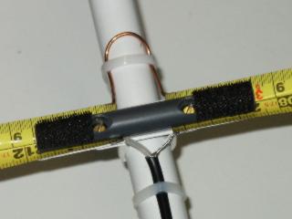
I found it necessary to reduce the length of the hairpin coil from 5″ to 4″, probably because the coax and hairpin connection points were on opposite edges of the tape elements.
CONSTRUCTION.
BOOM
Cut the boom at least 600mm long, (700mm to give an extended handle).
Mark the fixing points for the elements and drill for a 4mm bolt (bottom) and 8-10mm access hole (top).
The saddle clips are bolted through the bottom wall of the boom only, the nut and shake-proof washer drop through the top hole. With this method the boom is not distorted by the bolt fixing.
Tip To ensure accurate alignment, draw a guide line along the length of the boom using a piece of 12mm L-section aluminium as the straight edge ( or similar).
ELEMENT SUPPORTS.
A must do: – make a template for marking and drilling the element fixing holes from a scrap of 100mm long aluminium flat or section, drilled for 2no. 4mm holes.
The three bottom element supports are cut from a single 100mm length of 20-22mm PVC, then cut length-ways into 3 pieces, each piece having a 120 degree cross section of the pipe.
Drill the bottom element supports for 2 no. 4mm diameter bolts.
Tip: Cut out a paper template 69mm x 10mm, and mark two division lines 23mm apart. Wrap this round the pipe to mark the position of the cut lines. Use a tenon saw to give a straight cut.
Cut three lengths of 12 – 15mm plastic tube, 100mm long, for the element top clamps.
Drill the element top clamps for 2 no. 4mm diameter bolts.
Enlarge the top holes to 8-10mm to allow the nut head and washer to drop through. (similar to the boom fixing holes)
Drill a single 4mm hole in the centre of the saddle clip.
Tip:The vertical stroke in the character ‘R’ in the trademark stamp punched on the saddle clip, marks the centre position
TAPE ELEMENTS
Cut the 4 lengths of tape measure steel carefully to length, using a sharp pair of scissors (don’t tell the XYL!). Chamfer off the corners at the cut ends for safety.
Forming the holes in the tape is a breeze if you have a leather hole punch tool. You will need to secure a suitably sized washer to the anvil to punch through the tape.
If you do not have a punch, try starting with a pin hole then ream the hole out to the required size.
Take the paint off the underside inside corners of the driven element halves and tin.
Form the hairpin match from stiff wire round some 22mm pipe. The Wire length is 100mm plus 6mm each end for the solder legs (112mm total).
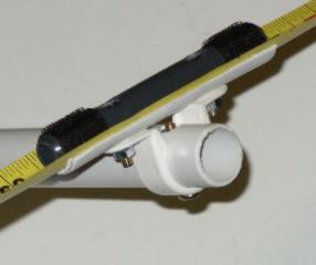
To assemble the elements, use 4mm x 25mm bolts with shake-proof washers. Bolt on the PVC wall clips to the bottom of the boom wall , but don’t tighten at first as the fixing lugs will spread and make it difficult to fix align the holes in the element support components.
Add a double-sided sticky pad to the underside of each element half and attach the driven elements to the element bottom support. The pads will prevent the possibility of the driven element half rotating around the single bolt fixing.
Solder on the hairpin and coax feed and secure both to the boom with cable ties.
Cover the sharp cut ends of the elements with insulation tape or similar, to protect users and passers-by ! I used a piece of Velcro tape on the ends and matching pieces on the top element clamps, this provided a means of ‘folding’ the elements for safely transporting the beam.
BALUN
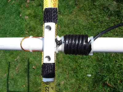
Not everyone has found the need for a balun, but if you do, 7 turns of the coax feed wound round the boom does the trick.
Material List
| Item | Material | Quantity | Note | |
|---|---|---|---|---|
| Boom | 21.5mm Marley pvc overflow pipe | 600mm min | See text | |
| Elements | 25mm steel measure tape | 3m | 1060, 2x 460, 900mm | |
| 25x25mm Velcro adhesive pad | 6no. | optional | ||
| Element supports | Top: 12mm plastic tube (or similar e.g. 15mm conduit) | 300mm | 3 x 100mm | |
| Bottom: 22mm PVC pipe | 100mm | cut length ways into 3 | ||
| 4mm x 25mm long bolts, with nut and shake proof washers. | 3 no. | |||
| 4mm x 12mm long bolts, with nut and shake proof washers. | 6 no. | |||
| 20x20mm double sided sticky pads | 2no | |||
| Marley 21.5mm saddle clips | 3no. | |||
| Feed | Coax & plug | |||
| Match | Stiff Wire |
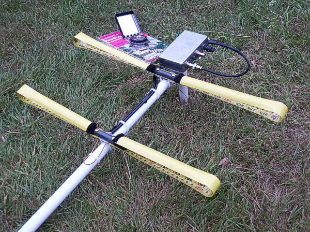
View showing the use of Velcro on the element ends to fold the elements.
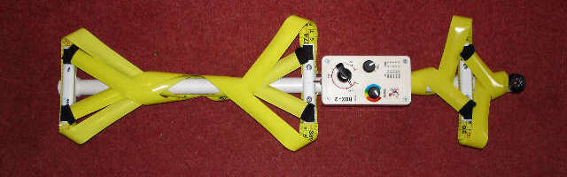
A more compact method of folding the elements! (integrated with the ROX-2 receiver)
Many thanks must go to Joe WB2HOL, for this assistance with this project.
LINKS TO REFERENCES AND FURTHER READING
Tape Measure Beam Optimised for Radio Direction Finding by Joe Leggio WB2HOL
Beta Coils and Hairpins The original L.B. Cebik web site is now hidden behind passwords and subscriptions, this is an alternative link. (10-2014).
YagiCad 4.1Yagi modelling software
QuickYagiYagi modelling software
YagiMax 2.2 Yagi modelling software – by K4VX
Shortened 2 elems foxhunting antenna by PE5EDW
Pingback: Direction Finding – Easy – Catch them Jammers | ve3ips