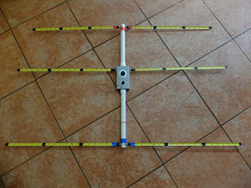
This 3 element yagi type is internationally used and has been adopted for use with the ROX-2X rather than the WB2HOL design used in the previous 2004 design.
There is no significant difference in the performance between the two yagis, but this design results in more balanced unit, when holding the ARDF unit with the integral receiver box.
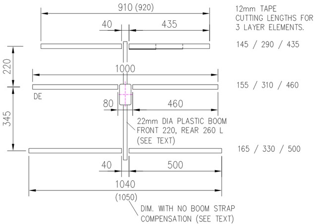
The dimensions for the yagi are shown above. Note that the director and reflector length are 10mm shorter than normal, to allow for the boom mounting method.
Receiver Box
The RX pcb is mounted in a standard die-cast box, size 110 x 60 x 30. Be aware that some cheaper aluminium boxes are not really suitable, having a high ‘draw’ (i.e. the sloping sides). In this case if the boom is attached as shown below, then there will be a noticeable bend in the length of the antenna. Hammond and Eddystone brand boxes are OK. Alternatively, although more expensive, a plastic box with RFI coating is easier to work, and results in a lighter construction.
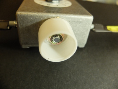
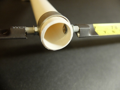
The boom sockets on the ends of the receiver enclosure are standard furniture feet protectors for 22mm tubing.These will need to be made from hard plastic, not rubber ! The sockets are fixed to the box with M6x12mm roofing bolts. To provide a secure fixing, which will not rotate, use double sided tape between the socket and the box. A large washer and nut goes inside the socket.
Element Connection
Boom to Element Connection showing
Boom strap and plastic ‘compression spring’
The removable antenna elements are fixed to the boom and receiver box using a M3 bolt assembly. For the boom, an aluminium strap around the outside of the boom connects the halves of the reflector and director elements.
The boom strap is made from thin aluminium sheet cut to 50x12mm with 2no. 3mm diameter holes spaced 35mm.
A ‘compression spring’ made out of Hama plastic beads (childrens craft toy) secures the elements. These should only be lightly tightened otherwise they will be damaged. Not really a problem to replace, when a bag of 1000 costs less than £2 ! ‘Real’ compression springs could be used, but sourcing them, and devising a retaining mechanism is not so easy.
The bolt assembly for the boom-to-element connection is as follows :-
- M3 x 16 countersunk head bolt
- M4 shake proof washer (yes M4 ! for countersunk bolt, gives larger bite area)
- (boom)
- M3 plain washer
- M3 nut
- M3 plain washer
- Hama plastic bead
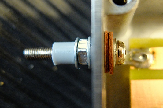
Insulated Connection to the Driven Element
The insulated bolt assembly for the box-to-element connection. This might need varying according to the box you are using (wall thickness and material). Fibre washers need to go on the inside of the box because they will absorb water.
- M3x20 bolt, standard head.
- M3 solder tag
- 2 M4 fibre washers (RS part 526-366), or nylon (RS part 525-739)
- (box wall)
- M3x3 Nylon Screw Insulator. (RS part 178-664)
- M3 plain washer
- M3 nut
- M3 plain waster
- Hama plastic bead.
Element Construction
This is simple to describe, but hard work to achieve, with so many pieces !
A M3X10 threaded spacer is soldered to the element ends, for the connection to the boom.
The elements are 3 layers thick at the supported end to provide extra stiffness.
- Cut the 18 lengths of 12mm tape to the dimensions shown above, you will need salvage two 3m tapes to do this.
- Remove 12mm of paint, both sides and tin one end of the each element part. Use lots of flux and a solder pot , if you have one.
- Prepare the M3X10 spacer, rough and tin one face.
- Assemble the 3 element parts, with the short length on the bottom, and the spacer on top of the longer length. It is essential to use a jig, however crude you make it, so the parts are secure and correctly aligned before soldering.
- Solder together using an Air Solder Blower Gun or, as I prefer, a paint stripper gun.
- Apply four short lengths of heat shrink tubing to each join (see top photo). If you are wealthy, you could cover the whole length!
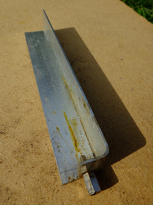
Jig, made from Aluminium Angle
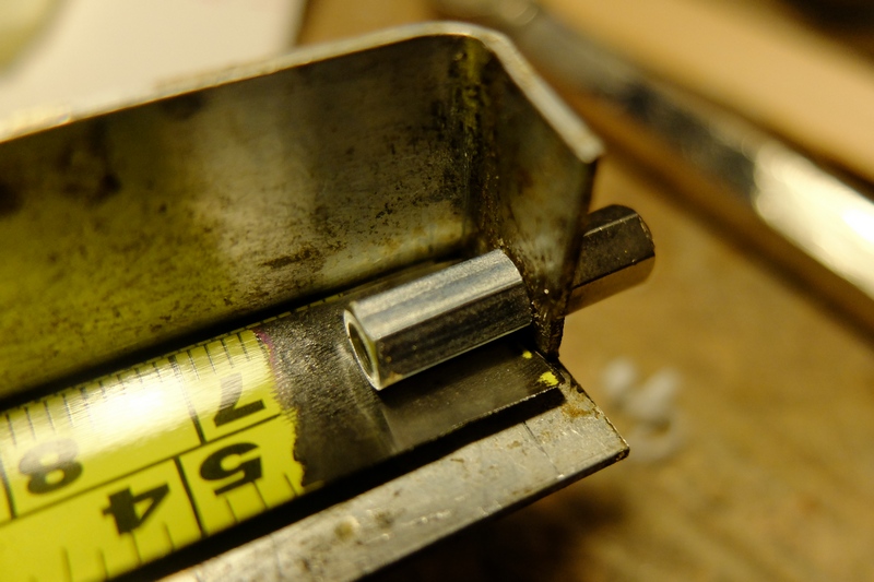 Spacer and 3 tape layers clamped together ready for soldering. (all parts should be tinned first, but not shown here)