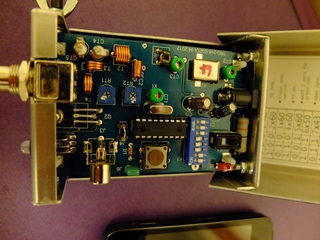
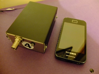
This version of the 2m ARDF Transmitter, has a reduced pcb size designed to sit over a 6xAA battery pack, which allows it to be housed in an enclosure half the size of previous versions.
Nearly all the R & C components are now surface mount.
With no external controls, the TX layout, provides a tamper free unit after timer had been set.
Just place in a plastic bag to keep it dry

By enlarging the existing fixing holes in the top cover of the enclosure into slots, the top can be hinged, allowing easy access when priming the unit.
A similar but larger box is used for the ATX80m TX by G3ZOI.
click here for a more detailed description for adapting the box.
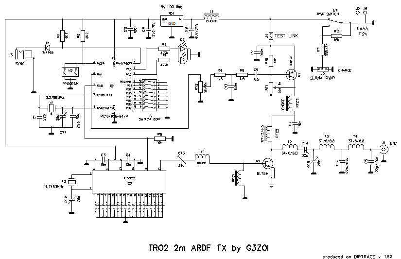
The TX is developed from designs by VE2EMM (RF strip), ON7YD (PIC timer) and DL3BBX (AM modulator).
It provides a complete, boxed ARDF TX suitable for Region-1 format events, with AM/MCW used for the CW ident.
The 6 x AA battery pack means a lower output of 0.25 – 0.5 watts when using standard Ni-Mh batteries, but in practice this is more than enough power. New Ni-Zn have just become available giving 1.6v per cell, which would double the output power. Though I have a set of these batteries this has not yet been tried ( August 2013 ).
Using a 7 or 8 AA cell pack will increase the output to 1watt.
PIC TIMER SOFTWARE
The basic timing and event format of the ON7YD PIC software has been adopted. but the PIC outputs MCW tones instead of a keyed CW output, eliminating the need for a separate tone generator.
The MCW square wave output, passes through a simple low pass filter, into a PNP, high gain darlington pair transistor, to modulate the PA.
A tactile switch is provided to allow an end-of-transmission callsign to be loaded into the pic EPROM
The PIC16F84 is no longer suitable for the latest code and the cheaper and more powerful PIC16F628 is used. The MCW tone is generated by the second timer in the PIC16F628 ( M0ETA code). The result is a clean audio tone, free from any digital clicks or buzz.
See the PIC software page on this site for more information.
Boxing
The TX was designed to fit a standard folding box type AB9 102x70x38mm. Unfortunately, at the time of writing these now seem to be very hard to find. Maplin have a few left (Sept 2014).
In the unit shown in the photo above the PCB is mounted on 5mm nylon supports, stuck to a 6xAA flat battery pack. The whole assembly drops into the top of the box.
The BNC needs a U-shape cut out on the front panel. The flange on the back panel needs to bent over flat.
Two M3 solder tags retain the pcb to the back panel, and the BNC socket at the front.
The box top hinges. The fixing holes need enlarging to slots. (See the web page for the ATX-80).
You will need an insulating sheet under the battery pack. that’s it !!
GENERAL NOTES ABOUT USING THE ICS525
To minimize phase noise with the ICS525R, select a xtal/multiplier combination that uses the lowest divider ratios ( see the ICS web-site for more details). The combination of uncertain resonant frequency and multiplier inaccuracies means you will probably have to do some trial and error testing to get clean output on the required channel.
For example :- using 14.746Mhz xtals, programmed with setting derived from the ICS web site for 144.500Mhz. The ‘pulling range’ is approximately 0 to 30Khz higher, giving the required output at 144.525Mhz
Multiplier combinations generating high phase noise, will degrade the quality of the AM.
Suggested Standard Xtals (30pF load)
(calculated design frequency in brackets)
target f =144.525MHz
- 14.746 (144.507)
- 10.240 (144.498)
target f=144.775MHz
- 14.318 (144.773)
- 18.192 (144.725)
- 12.288 (144.725)
Downloads
WWW REFERENCES AND FURTHER READING
- ARDF Site of Rik Strobbe ON7YD
- The Montreal Project – VE2EMM
- Siegfried Pomplun DL3BBX Transmitter (PDF)
- ICS525R frequency calculator (Calculator No Longer Available !)
ALSO ….
You will also need the following to complete your transmitter control station.
- Antenna. Construction details
- Control flag and pin punch from Compasspoint


Well done, thanks,
Hello.
I also built some TX (almost same schematic and controlled by PIC) and beacons (controlled by ARM with 2 cristalls). Now I’d like to try PLL for it. Thanks for information.