 | ||
| CLICK HERE TO GO TO NEW WEB SITE | ||
A 1-Watt AM/FM Transmitter for 144Mhz Radio Orienteeringby G3ZOI( updated Jan 2010 )
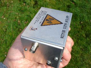
With no external controls, the TX layout, provides a tamper free unit after timer had been set. Just pop it into plastic bag to keep it dry!
The same box is used for the ATX80m TX by G3ZOI. CONSTRUCTION DETAILSThe TX is developed from designs by VE2EMM (RF strip), ON7YD (PIC timer) and DL3BBX (AM modulator).It provides a complete, boxed ARDF TX suitable for Region-1 format events, with AM/MCW used for the CW ident, with FM/MCW available as an alternative  The TX specification gives :- 250-1000 mW output. Continuous carrier with AM, tone modulated CW
ident.
2N4427 PA (n.b. not suitable for latest PCB)Earlier designs allowed either the 2N2247 or BLT50 to be used in the PA. Generic 2N4427s will typically give the minimum specified gain of 10dB, so you can expect at least 300mW. Genuine Motorola 2N4427s typically give 12dB gain, so the output will be nearer 500mW.The modulation transistor lowers the available voltage to the 2N4427, so the carrier output is less than potentially available with FM or CW modes. 300mW has proved to be more than adequate for regular ARDF events, and the low current requirement means the TXs will run for very long periods on AA rechargeable batteries. BLT50 PAThe BLT50 is a surface mount 1 watt / 10db gain device, intended for use at 470Mhz.At 144Mhz the gain is considerably higher than 10db, such that 1 watt output is easily attained at 144Mhz in AM mode. The BLT50 also requires a lower supply voltage. Using a battery pack with 7xAA cells and a dummy cell (9v nom.) is recommended to limit the PA voltage and RF output. Although 8 cells can be used, in practice most of the power from the addition cell is likely to be dissipated by the BD686, which will then get quite hot! The current supply will be higher than the 2N4427 version (approximately 270ma), but with modern AA/NiMH batteries, and only a 25% duty cycle, the battery pack will give many hours of service. 100% AM modulation is now obtainable, with less downward modulation than experienced with the 2N4427. 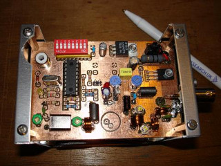
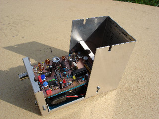
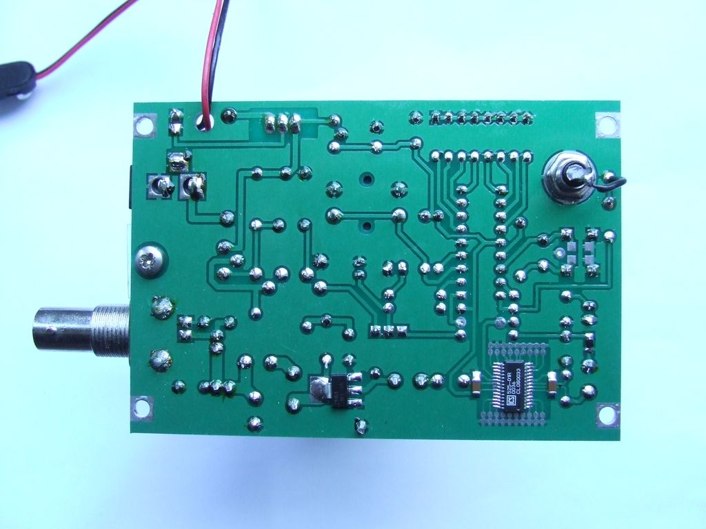
Photo Left. (early prototype) TX with the top cover removed. The BLT50 is on the underside of the PCB. Note the cut-out for access to the phono sync socket. PIC TIMER SOFTWAREThe basic timing and event format of the ON7YD PIC software has been adopted. but the PIC outputs MCW tones instead of a keyed CW output, eliminating the need for a separate tone generator.The MCW square wave output, passes through a simple low pass filter, into a PNP, high gain darington pair transistor, to modulate the PA. The MCW output can be switched to provide FM modulation. A tactile switch is provided to allow an end-of-transmission callsign to be loaded into the pic EPROM The PIC16F84 is no longer suitable for the latest code and the cheaper and more powerful PIC16F628 is used. The MCW tone is generated by the second timer in the PIC16F628 ( M0ETA code). The result is a clean audio tone, free from any digital clicks or buzz. See the PIC software page on this site for more information. GENERAL NOTES ABOUT USING THE ICS525To minimize phase noise with the ICS525R, select a xtal/multiplier combination that uses the lowest divider ratios ( see the ICS web-site for more details). The combination of uncertain resonant frequency and multiplier inaccuracies means you will probably have to do some trial and error testing to get clean output on the required channel.For example :- using 14.746Mhz xtals, programmed with setting derived from the ICS web site for 144.500Mhz. The 'pulling range' is approximately 0 to 30Khz higher, giving the required output at 144.525Mhz Multiplier combinations generating high phase noise, will degrade the quality of the AM.
Suggested Standard Xtals (30pF load)(design frequency in brackets)target f =144.525MHz
target f=144.775MHz
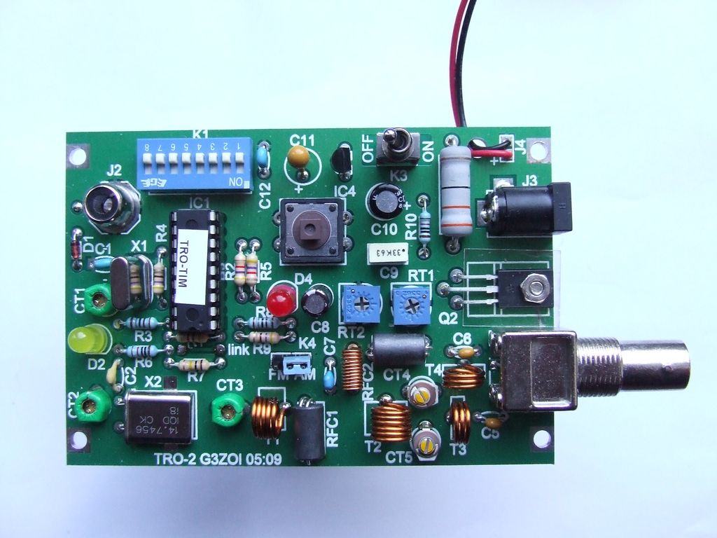
PCBs Commercial grade PCBs are available with or without the ICS525 fitted
and tested.
Commercial grade PCBs are available with or without the ICS525 fitted
and tested.The PCB development was sponsored by John Little M1SHE of Shearwater ECM. N.B. Boards dated 01.08 and after, are pre-wired for a 14.746 MHz xtal and 144.500-144.525 output. Other frequencies will require the cutting or bridging of the earthing ports of the ICS525.
PDF DOWNLOADSGeneralFor PCB date stamped 05:09For PCB date stamped 01:08For PCB date stamped 02:06
WWW REFERENCES
ALSO ....You will also need the following to complete your transmitter control station.
G3ZOI
| ||