
AN 80M TRANSMITTER FOR RADIO ORIENTEERING
by G3ZOI - page updated - AUG 2011
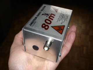
The 80m TX described here is the well known ON7YD ATX-80 and timer, combined and re-engineered
to fit a readily available enclosure.
For a full description of this excellent design visit the ON7YD web site
The PIC timer and RF circuits have been combined and a PCB designed to fit a
standard AB28 folder aluminium box.
This is the same enclosure system adopted for the 2m ARDF TX.
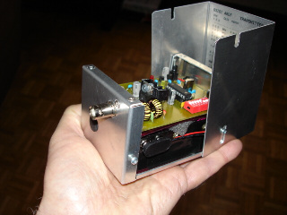
The AB28 box is ideal because it neatly accommodates a 10xAA battery pack
with the main PCB above.
In operation, the unit is placed in a plastic bag and hidden under leave mould.
A plastic storage box, or plastic pipe might be other weather proofing alternatives.
Commercial grade PCBs are available from the author (subject to availability).
 |
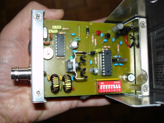 |
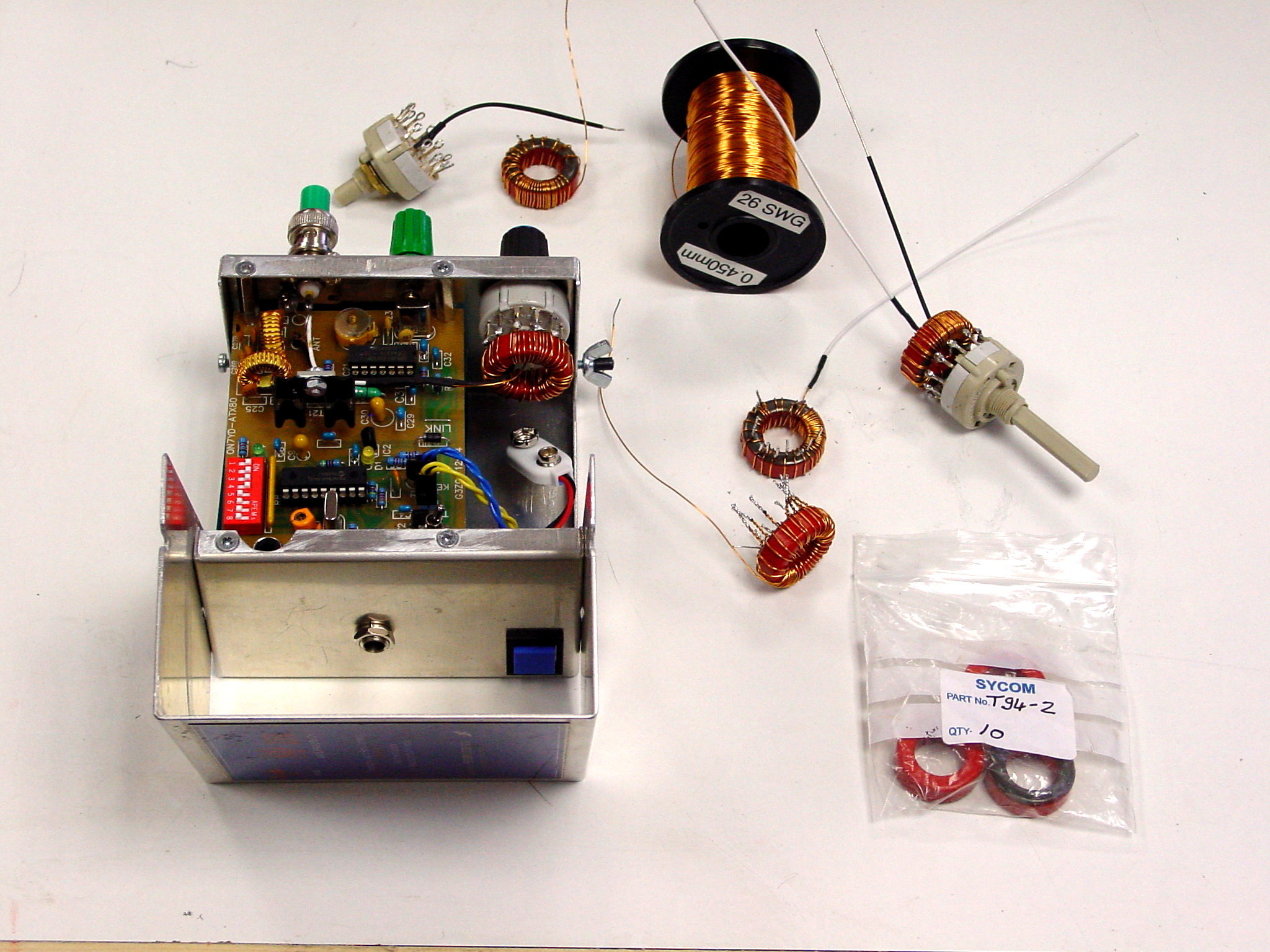
John Little M1SHE has constructed the TX
with a slightly wider aluminimum box
(Type NB23 102x102Xx64mm : from CPC.co.uk : part number EN81250).
This allows the inclusion of a simple toriod matching device,
switched on the front panel
An additional DPDT switch on the back
facilitates TX and Key-ON for tuning |
 |
PIC SOFTWARE
You can use the original software by ON7YD or alternatively the
G3ZOI software, which has been enhanced to allow an end-of-transmission callsign to be
programmed into eprom.
MATCHING ANTENNA
For details of a suitable 80m ARDF Antenna click here
VERSION-3 PCB dated 12:09
OLDER VERSIONS
UPDATE : NO NEED TO CUT ONE FLANGE AS SHOWN BELOW, JUST FOLD IT FLAT TO THE ENCLOSURE BOTTOM.
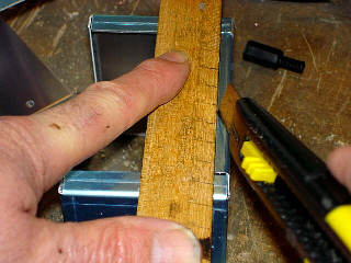
Photo left.
One side of the bottom flange needs to be cut down to half its height.
This will allow you to remove the battery pack.
Score the flange, with a hobby knife
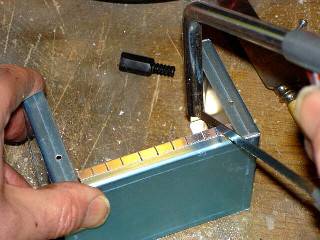
Photo right.
Cut several fingers (not yours!) with a hacksaw, down to the score line.
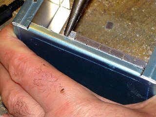
Photo left.
Break off the fingers with some long-nose pliers,
then file the break line
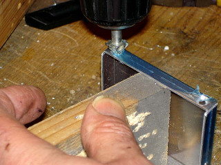
Photo right.
Drill and countersink the fixing holes for the PCB spacers.
The spacers hang from the top flange.
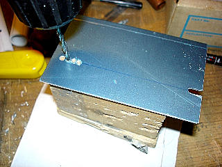
Photo left.
Enlarge the existing fixing holes in the box-top to allow it to hinge.
Only other work required is to cut a notch for the sync socket ( see top view above) and
the holes for a BNC socket.
| 


