ROX-2T ARDF RECEIVER (PCB 12:09) ROX-2T ARDF RECEIVER (PCB 12:09)
(All the photos will open individually at a higher resolution )
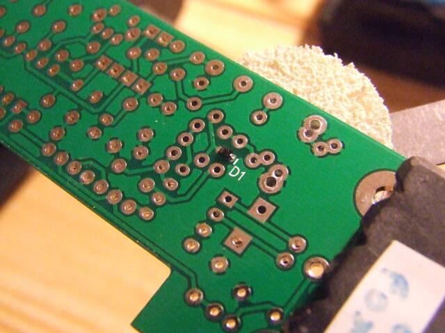 |
Location of the SMT varicap on the under side of the board. The
cathod end is banded. Illumination with a LED light/torch, will render
the banding very clearly.
|
|
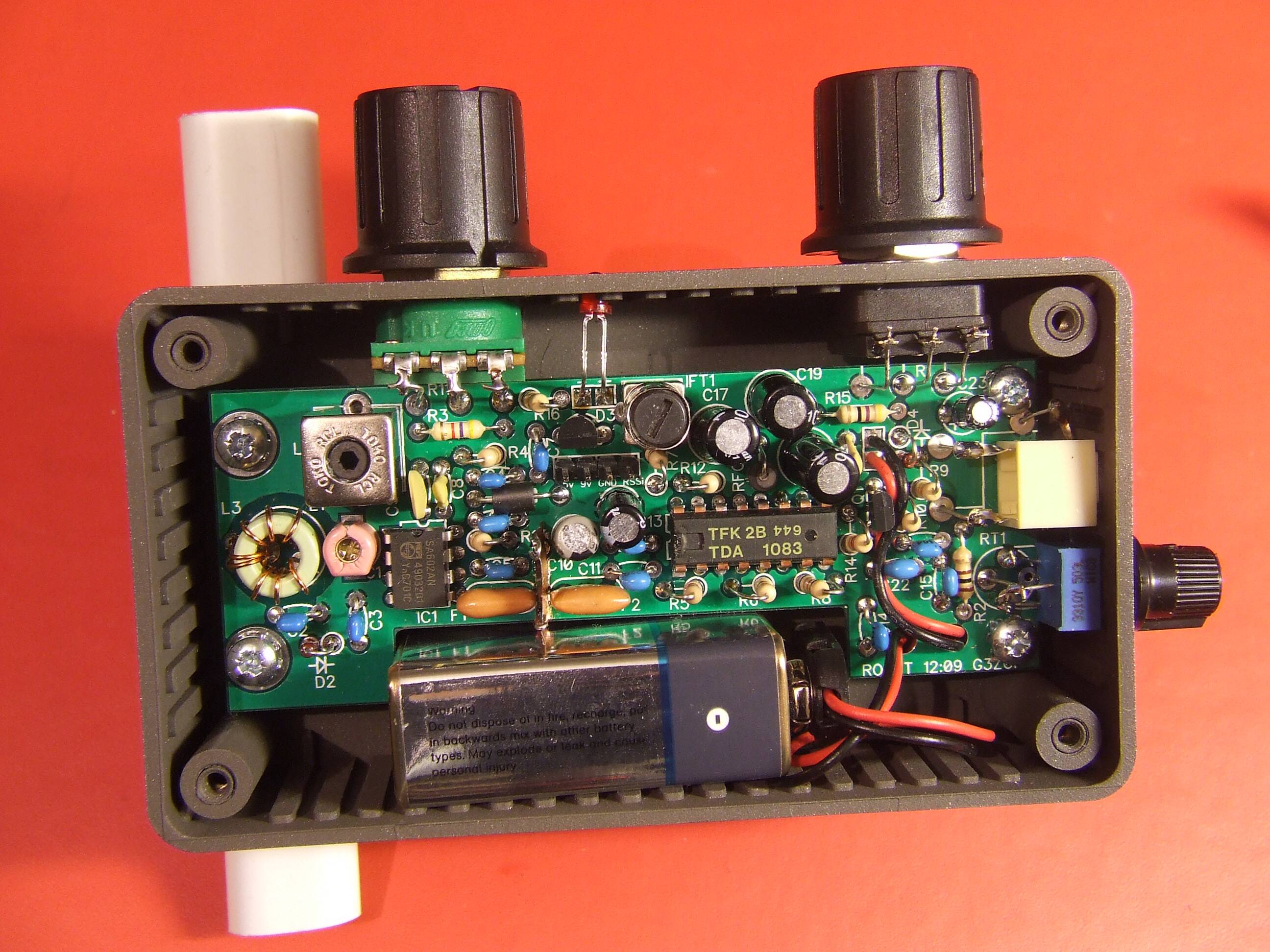
This is a high resolution plan view of the assembled PCB. |
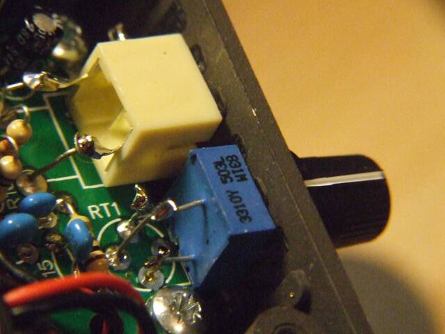 |
RT1 can be a 100K trimmer, or a 9mm pot, as shown.
However, please note
- If a pot is used, the PCB cannot be assembled or removed with the pot in place.
- The pot should used as secondary to the gain control as it reduces the audio dynamic range.
|
|
|
|
|
|
|
|
|
|
|
|
|
|
|
|